
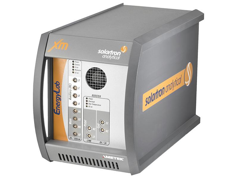
Solartron EnergyLab XM儲能電化學分析儀
- ±2A大電流範圍,未來可搭配±100A 外部電流放大器
- 四對輔助分壓量測端,滿足電池Anode/ Cathode/ 全電池的同時阻抗量測
- 全新Solatron操作軟體XM-Studio,內建EIS fitting功能
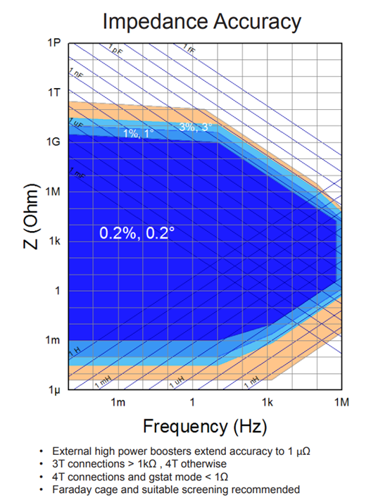
- 維持Solartron傳統的高標準,EnergyLab XM擁有一流的交流阻抗量測精度
EnergyLab XM 是Solartron專為儲能應用設計之儀器,依電池、燃料電池和超級電容器的研究而設計。 EnergyLab XM 的極高靈敏度用於鋰離子電池和鹼性電池的進階測試。這包括對半電池配置和低於 100 μΩ 範圍的下一代低阻抗電池以及流行電池類型(如 2032 紐扣電池測試和 18650 電池測試)的研究。
EnergyLab XM 包括參考級恆電位儀、恆電流儀、頻率響應分析儀 (FRA)、輔助電壓通道和 2A 升壓器。這些功能為最常見的阻抗和電池容量(充電放電)測試提供了準確性,以測量電池可以提供的額定容量(毫安培時)或能量(瓦時)。
電池測試可能需要高電流,以高放電率對電池進行完全充電或完全放電,或測量低阻抗。 EnergyLab XM 可連接高達 100 A 的外部功率放大器。我們的助推器是自動控制的,可進行完全整合的測試。
所有模式(恆電位儀、恆電流儀...增強型和非增強型)均利用 Solartron Analytical 獨特的輔助通道功能。這些輔助通道可以測量電池組中單一電池的電池端子之間的標稱電壓,或測量陽極、陰極、隔膜之間的電池級電壓。同時協調測量直流和阻抗可以識別電池故障模式並預測電池壽命。
維持Solartron傳統的高標準,EnergyLab XM擁有一流的交流阻抗量測精度,Solartron為整個頻率範圍內的 EIS 提供最高精度的交流技術 - 單正弦波、多正弦波、諧波、互調。結果是高度可重複的低於 100 μΩ 的測量,適用於最苛刻的應用。
| Potentiostat/Galvanostat | |
| Cell connections | 2, 3, or 4 terminal |
| Instrument Connections | CE, WE, RE, LO |
| Floating measurements | yes |
| Impedance measurement bandwidth | 1 MHz (via FRA) |
| Maximum time record | Unlimited |
| Counter Electrode (CE) | |
| Smooth “analog” scan generator | 64 MS/s interpolated and filtered |
| Voltage polarization (and compliance) range | ± 8V |
| Current polarization range | Pstat ±300 mA Booster ±2 A |
| Recommended voltage scan rate | 25 kV/s to 1 µV/s |
| Recommended current scan rate | 1 kA/s to 200 µA/s |
| Bandwidth (decade steps) | 1MHz to 10 Hz |
| Polarization V/I error (setting+range) | 0.1% + 0.1% |
| Minimum pulse duration | 1 µs |
| Slew rate | >10 V/µs |
| Rference Inputs (RE) | |
| Connections | Differential input |
| Cable Shields | Driven (3T) / Ground (4T)for ±10V signal = 300µV |
| Maximum voltage Measurement | ±8 V |
| Ranges | 8 V to 3 mV |
| Accuracy (reading % + range % + offset) | 0.1% + 0.05% + 100 µV |
| Maximum resolution | 1 µV |
| Input impedance | >100 GW, |
| Input bias current | <10pA |
| Maximum ADC sample rate | 1 MS/s |
| Working Electrode (WE) | |
| Maximum current | Pstat ±300 mA Booster ±2 A |
| Ranges | Pstat 300 mA to 30 nA Booster 3 A to 30 nA |
| Accuracy (reading % + range % + offset) | ±0.1% + 0.05% + 30 fA |
| Maximum resolution | 1.5 pA |
| Compliance voltage range (floating) | ±8 V |
| Maximum ADC sample rate | 1 MS/s |
| Auxiliary electrodes (A, B, C, D) | |
| Differential Auxiliary Electrodes | 4 (same spec. as RE) |
| DC Measurement | Synchronized to RE |
| Impedance measurement bandwidth | 1 MHz (via FRA) |
| Frequency Response Analyzer | |
| Maximum sample rate | 40 MS/s |
| Frequency range | 10 µHz to 1 MHz |
| Frequency resolution | 1 in 65,000,000 |
| Frequency error | ±100 ppm |
| Minimum ∫ time per measurement (single sine, FFT or harmonic) | 10 ms |
| Signal Output | |
| Waveform | Single sine, multi-sine Single Sine |
| Single sine | Linear / logarithmic |
| Multi-sine / harmonic frequencies | All or selected |
| Analysis channels | |
| Accuracy (ratio) | ±0.1%, ±0.1° |
| Anti-alias, digital filters, DC bias reject | Automatic |
| Analysis channels | RE, WE, Aux A/B/C/D |
| Analysis modes: | Single sine, FFT, harmonic |
| DC Bias rejection | Automatic |